
When machinery fails unexpectedly, the culprit often lies in a seemingly minor component specification that was overlooked during selection.
Bearing tolerances represent one of the most critical yet misunderstood aspects of mechanical design, directly impacting everything from operational accuracy to equipment lifespan. Understanding tolerance class specifications isn’t just about meeting engineering requirements; it’s about optimizing performance while controlling costs.
The challenge lies in navigating the complex landscape of standardized tolerance systems.
From ABEC ratings used in American applications to ISO classifications prevalent in international markets, each system presents unique numbering conventions and measurement criteria.
Add specialized requirements for different bearing types – and the selection process becomes increasingly complex.
- ball bearings
- roller bearings
- tapered configurations
This comprehensive guide demystifies tolerance specifications across all major standards, providing actionable insights for mechanical engineers, maintenance professionals, and procurement specialists. You’ll discover how dimensional deviation impacts real-world performance, when to justify premium precision classes, and how to match tolerance requirements with application demands.
By mastering these fundamental concepts, you’ll transform tolerance selection from guesswork into strategic advantage, ensuring optimal component performance while maximizing return on investment across your mechanical systems.
More importantly, you’ll learn to recognize the difference between marketing specifications and actual performance characteristics that truly drive operational success.
What Are Bearing Tolerances & Why Do They Matter?
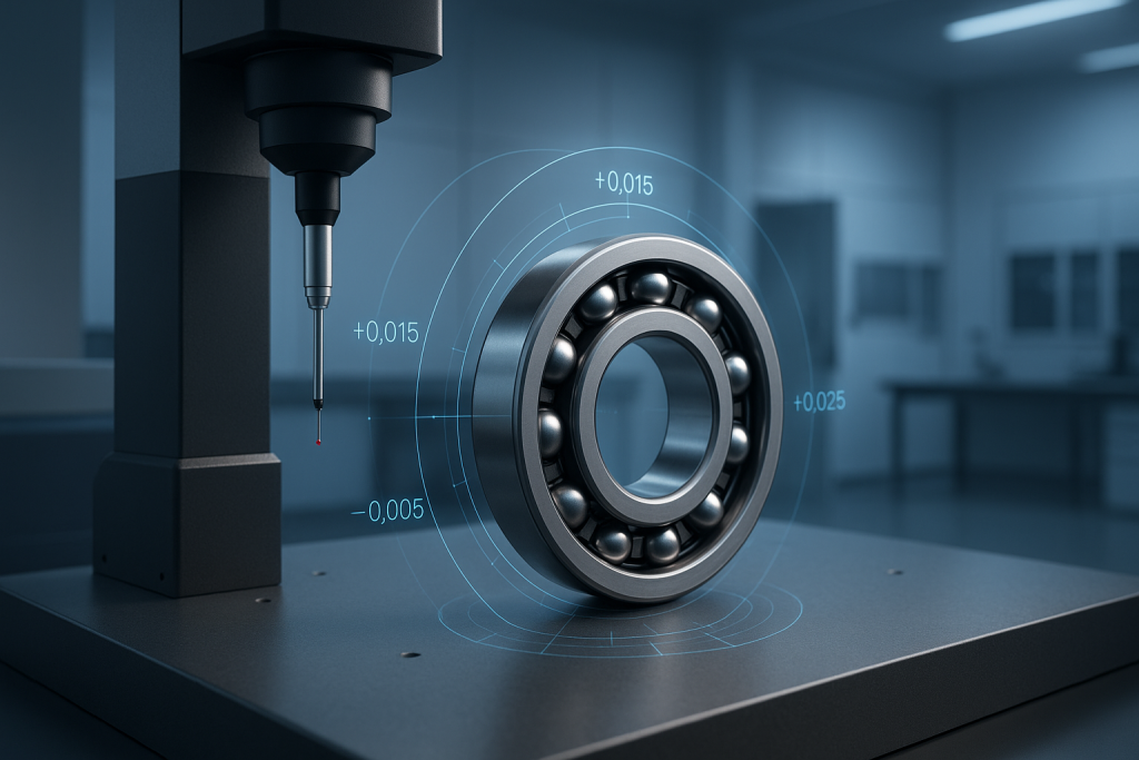
Bearing tolerances define the permissible dimensional deviation from nominal specifications, controlling how precisely manufactured components will perform in real-world applications. These tolerances encompass three critical accuracy parameters:
- Dimensional Accuracy (bore diameter, outer ring dimensions, and width)
- Form Accuracy (roundness, cylindricity)
- Running Accuracy (radial runout, axial movement)
Think of tolerances as the difference between a component that fits perfectly versus one that causes vibration, premature wear, or catastrophic failure. When a shaft diameter varies by even micrometers beyond specified limits, the resulting misalignment can generate excessive stress, heat, noise, and dramatically reduce operational lifespan. Conversely, overly tight tolerances may unnecessarily increase procurement costs without delivering proportional performance benefits.
The tolerance class directly influences critical performance characteristics including speed capabilities, load capacity, and operational precision. Higher precision classes enable smoother rotation at elevated speeds while reducing vibration levels that can damage adjacent components. However, achieving tighter tolerances requires advanced manufacturing processes, specialized quality control, and premium materials – factors that significantly impact pricing.
Understanding these relationships empowers better selection decisions. A standard industrial application may perform optimally with Class 0 tolerances, while high-speed spindle applications require Class 5 or higher precision. The key lies in matching tolerance requirements to actual operational demands rather than defaulting to either the cheapest or most expensive options available.
Most importantly, tolerance specifications must align with housing and shaft tolerances to achieve proper fit conditions. A precision component installed with inadequate shaft preparation will underperform compared to a standard tolerance component properly installed. This systematic approach to tolerance matching ensures maximum return on investment while preventing costly operational failures that could have been avoided through proper specification.
These 4 Key Standards Are the Key to Understanding Bearing Tolerances
Navigating the world of precision manufacturing requires familiarity with four primary tolerance standards that govern global markets. Each system developed independently but now offers equivalent precision classes, enabling cross-reference between manufacturers and applications worldwide.
1. ABEC (Annular Bearing Engineering Committee)
The American standard uses ascending odd numbers (1, 3, 5, 7, 9) where higher values indicate tighter tolerances. ABEC-1 represents basic precision suitable for general industrial applications, while ABEC-9 delivers ultra-precision for specialized aerospace and medical equipment. This system predominates in North American markets and aligns with ANSI specifications.
2. ISO (International Organization for Standardization)
The globally recognized ISO 492 standard employs a descending numbering system where lower numbers indicate higher precision. Normal precision starts at Class 0, progressing through P6, P5, P4, to P2 for ultra-precision applications. Most international manufacturers reference ISO classifications, making this the most widely applicable standard.
3. DIN (Deutsches Institut für Normung)
German engineering standards mirror ISO classifications with identical numbering conventions. DIN 620 specifications often appear on European-manufactured components and maintain strict equivalency with ISO tolerances. This standardization facilitates seamless component interchange between suppliers.
4. JIS (Japanese Industrial Standards)
Japanese manufacturers utilize JIS B1514 standards that closely parallel ISO classifications. The numbering system follows the same descending precision convention, with Class 0 representing normal tolerance and Class 2 indicating ultra-precision manufacturing.
Understanding these equivalencies eliminates confusion when sourcing components from different manufacturers or regions. A P5 tolerance class delivers identical performance whether specified under ISO, DIN, or JIS standards, while ABEC-5 provides equivalent precision through the American system. This standardization ensures reliable component interchange and simplifies global procurement processes.
Leverage Bearing Tolerances to Your Advantage: 7 Action Steps for Better Selection
Transforming tolerance specifications from confusing technical jargon into operational advantages requires a systematic approach. These seven proven steps eliminate guesswork while ensuring optimal component selection for your specific application requirements.
1. Assess Your Speed Requirements
High-speed applications demand tighter tolerances to minimize vibration and heat generation. Components operating above 3,000 RPM typically require Class 5 (ABEC-5) or higher precision to maintain stable operation. Standard industrial speeds below 1,500 RPM often perform adequately with Class 0 tolerances, providing significant cost savings without compromising reliability.
2. Evaluate Your Environment
Operating conditions directly influence tolerance requirements. High-temperature environments, contaminated atmospheres, or applications with shock loading may benefit from specific tolerance combinations that enhance durability. Consider how dimensional changes from thermal expansion might affect fit conditions throughout the operating cycle.
3. Calculate Total Cost of Ownership
Premium tolerance classes cost more initially but often deliver superior operational lifespan and reduced maintenance requirements. Factor replacement frequency, downtime costs, and energy consumption when comparing options. A higher-precision component that operates 50% longer while consuming less energy often provides better long-term value.
4. Match Mounting Tolerances to Component Precision
The most precise component will underperform if mounted on poorly machined surfaces. Ensure shaft and housing tolerances complement your selected precision class. Standard mounting practices suffice for Class 0 components, while ultra-precision applications require specialized installation procedures and equipment.
5. Identify Critical vs. Non-Critical Positions
Not every position in your machinery requires identical precision levels. Main spindles and critical drive components justify premium tolerances, while auxiliary equipment may operate effectively with standard specifications. This selective approach optimizes performance while controlling procurement costs.
6. Specify the Complete Tolerance Code
Partial specifications create procurement confusion and potential misapplication. Include dimensional accuracy, radial runout, and any special requirements in your specifications to ensure suppliers provide exactly what your application demands.
7. Partner with Tolerance Experts
Experienced suppliers can recommend optimal tolerance combinations based on similar applications and provide technical support throughout the selection process.
Confused by Bearing Tolerances? Our Experts Help Simplify Your Selection
Technical specifications shouldn’t stand between you and optimal machinery performance. At Central Surplus, our engineering team transforms complex tolerance requirements into straightforward solutions tailored to your specific applications.
When standard catalogs don’t contain the exact specifications you need, our sourcing network delivers solutions. We maintain relationships with premium manufacturers across all major tolerance standards, enabling us to locate specialized components that meet your precise requirements.
Our team can cross-reference between different manufacturer specifications and identify equivalent alternatives when primary sources are unavailable, while providing ongoing technical support throughout your procurement process.
To discuss your tolerance requirements and discover how proper specification can enhance your machinery’s performance and reliability:
6 Detailed Tolerance Specification Charts: Numbers That Drive Your Productivity

Precise numerical specifications eliminate guesswork from component selection, providing the concrete data needed to match tolerance requirements with application demands. These comprehensive charts present tolerance values across all major precision classes, enabling direct comparison between different standards and manufacturers. Understanding these specific numerical ranges empowers confident selection decisions based on measurable performance criteria rather than vague marketing descriptions.
Each chart addresses critical dimensional parameters that directly impact operational performance. Inner ring bore diameter tolerances control shaft fit conditions, while outer ring dimensions determine housing compatibility. Running accuracy specifications define operational smoothness and vibration levels, while width tolerances ensure proper axial positioning within assemblies. These interrelated parameters work together to determine overall system performance and reliability.
The values presented reflect internationally standardized specifications that manufacturers worldwide must meet to claim compliance with specific tolerance classes. This standardization ensures consistent performance regardless of component source, enabling reliable procurement from multiple suppliers while maintaining identical operational characteristics. When applications require custom specifications beyond these standard ranges, specialized manufacturing processes can achieve tighter tolerances at premium pricing.
Reference these charts during the specification process to establish realistic performance expectations and cost targets. Higher precision classes deliver measurably superior performance in critical parameters but require proportionally higher investment. The key lies in identifying which parameters most significantly impact your application performance and specifying precision accordingly. This targeted approach maximizes performance benefits while controlling procurement costs through strategic tolerance selection.
1. Inner Ring Bore Diameter Tolerances (Micrometers)
Bore diameter accuracy directly controls shaft fit conditions and determines how effectively torque transfers from shaft to rolling elements. Tighter tolerances enable more precise fits while reducing the risk of fretting corrosion and premature wear. These values represent the permissible deviation from nominal bore dimensions across different precision classes.
| Bore Size Range | Class 0/ABEC-1 | Class 6/ABEC-3 | Class 5/ABEC-5 | Class 4/ABEC-7 | Class 2/ABEC-9 |
|---|---|---|---|---|---|
| 0.6mm - 2.5mm | +0/-8 | +0/-7 | +0/-5 | +0/-4 | +0/-2.5 |
| 2.5mm - 10mm | +0/-8 | +0/-7 | +0/-5 | +0/-4 | +0/-2.5 |
| 10mm - 18mm | +0/-8 | +0/-7 | +0/-5 | +0/-4 | +0/-2.5 |
| 18mm - 30mm | +0/-10 | +0/-8 | +0/-6 | +0/-5 | +0/-2.5 |
| 30mm - 50mm | +0/-12 | +0/-10 | +0/-8 | +0/-6 | +0/-2.5 |
| 50mm - 80mm | +0/-15 | +0/-12 | +0/-9 | +0/-7 | +0/-4 |
| 80mm - 120mm | +0/-20 | +0/-15 | +0/-10 | +0/-8 | +0/-5 |
2. Outer Ring Outside Diameter Tolerances (Micrometers)
Outside diameter specifications control housing fit conditions and influence heat dissipation characteristics. Proper tolerance selection ensures adequate support while allowing for thermal expansion. These tolerances become increasingly critical in high-speed applications where centrifugal forces affect dimensional stability.
| OD Size Range | Class 0/ABEC-1 | Class 6/ABEC-3 | Class 5/ABEC-5 | Class 4/ABEC-7 | Class 2/ABEC-9 |
|---|---|---|---|---|---|
| 2.5mm - 6mm | +0/-8 | +0/-7 | +0/-5 | +0/-4 | +0/-2.5 |
| 6mm - 18mm | +0/-8 | +0/-7 | +0/-5 | +0/-4 | +0/-2.5 |
| 18mm - 30mm | +0/-9 | +0/-8 | +0/-6 | +0/-5 | +0/-4 |
| 30mm - 50mm | +0/-11 | +0/-9 | +0/-7 | +0/-6 | +0/-4 |
| 50mm - 80mm | +0/-13 | +0/-11 | +0/-9 | +0/-7 | +0/-4 |
| 80mm - 120mm | +0/-15 | +0/-13 | +0/-10 | +0/-8 | +0/-5 |
| 120mm - 150mm | +0/-18 | +0/-15 | +0/-11 | +0/-9 | +0/-5 |
3. Running Accuracy Specifications (Micrometers)
Running accuracy parameters define operational smoothness and directly impact vibration levels, noise generation, and high-speed capabilities. Radial runout specifications control shaft centerline stability, while axial measurements govern thrust load distribution. These values prove critical for applications requiring minimal vibration or precise positioning.
| Bearing Size | Tolerance Parameter | Class 0 | Class 6 | Class 5 | Class 4 | Class 2 |
|---|---|---|---|---|---|---|
| 10mm - 18mm | Radial Runout Inner Ring | 10 | 7 | 4 | 2.5 | 1.5 |
| Radial Runout Outer Ring | 15 | 8 | 5 | 3 | 1.5 | |
| Axial Runout Inner Ring | 7 | 3 | 1.5 | 1.5 | 1.5 | |
| Face Perpendicularity | 7 | 3 | 1.5 | 1.5 | 1.5 | |
| 18–30mm | Radial Runout Inner Ring | 13 | 8 | 4 | 3 | 2.5 |
| Radial Runout Outer Ring | 15 | 9 | 6 | 4 | 2.5 | |
| Axial Runout Inner Ring | 8 | 4 | 1.5 | 1.5 | 1.5 | |
| Face Perpendicularity | 8 | 4 | 1.5 | 1.5 | 1.5 | |
| 30–50mm | Radial Runout Inner Ring | 15 | 10 | 5 | 4 | 2.5 |
| Radial Runout Outer Ring | 20 | 10 | 7 | 5 | 2.5 | |
| Axial Runout Inner Ring | 8 | 4 | 1.5 | 1.5 | 1.5 | |
| Face Perpendicularity | 8 | 4 | 1.5 | 1.5 | 1.5 | |
| 50–80mm | Radial Runout Inner Ring | 20 | 10 | 5 | 4 | 2.5 |
| Radial Runout Outer Ring | 25 | 13 | 8 | 5 | 4 | |
| Axial Runout Inner Ring | 8 | 5 | 1.5 | 1.5 | 1.5 | |
| Face Perpendicularity | 8 | 5 | 1.5 | 1.5 | 1.5 | |
| 80–120mm | Radial Runout Inner Ring | 15 | 10 | 5 | 4 | 2.5 |
| Radial Runout Outer Ring | 20 | 10 | 7 | 5 | 2.5 | |
| Axial Runout Inner Ring | 8 | 4 | 1.5 | 1.5 | 1.5 | |
| Face Perpendicularity | 8 | 4 | 1.5 | 1.5 | 1.5 |
4. Ring Width Tolerance Specifications (Micrometers)
Width tolerances ensure proper axial positioning and preload distribution in assemblies. These specifications become particularly important in back-to-back or face-to-face mounting arrangements where precise spacing affects operational characteristics.
| Bearing Size Range | Class 0/ABEC-1 | Class 6/ABEC-3 | Class 5/ABEC-5 | Class 4/ABEC-7 | Class 2/ABEC-9 |
|---|---|---|---|---|---|
| 0.6mm - 2.5mm | +0/-40 | +0/-40 | +0/-40 | +0/-40 | +0/-40 |
| 2.5mm - 10mm | +0/-120 | +0/-120 | +0/-40 | +0/-40 | +0/-40 |
| 10mm - 18mm | +0/-120 | +0/-120 | +0/-80 | +0/-80 | +0/-80 |
| 18mm - 30mm | +0/-120 | +0/-120 | +0/-120 | +0/-120 | +0/-120 |
| 30mm - 50mm | +0/-120 | +0/-120 | +0/-120 | +0/-120 | +0/-120 |
| 50mm - 80mm | +0/-150 | +0/-150 | +0/-150 | +0/-150 | +0/-150 |
| 80mm - 120mm | +0/-200 | +0/-200 | +0/-200 | +0/-200 | +0/-200 |
5. ABEC Precision Equivalency & Applications
Cross-reference chart enabling comparison between American ABEC standards and international ISO classifications. Application examples demonstrate typical use cases for each precision class, while cost multipliers indicate relative pricing expectations.
| ABEC Grades | ISO Class | Typical Applications | Speed Rating | Vibration Level | Cost Multiplier |
|---|---|---|---|---|---|
| ABEC-1 | Class 0 | General industrial, fans, pumps, conveyor bearings | Standard | High | 1.0x |
| ABEC-3 | Class 6 | Electric motors, automotive, appliances | Medium | Medium | 1.5x |
| ABEC-5 | Class 5 | Machine tools, precision equipment | High | Low | 2.5x |
| ABEC-7 | Class 4 | High-speed spindles, aerospace | Very High | Very Low | 4.0x |
| ABEC-9 | Class 2 | Ultra-precision instruments, medical devices | Ultra High | Minimal | 8.0x |
6. Miniature Bearing Tolerance Specifications (ABEC System)
Specialized tolerance ranges for miniature and instrument applications where space constraints demand compact designs without sacrificing precision. These applications often require tighter tolerances than standard industrial components to maintain performance in reduced envelope dimensions.
| Bore Diameter Range | Characteristic | ABEC-1 | ABEC-3P | ABEC-5P | ABEC-7P | ABEC-9P |
|---|---|---|---|---|---|---|
| Up to 10mm | Bore Tolerance Limits | +0/-12 | +0/-8 | +0/-8 | +0/-8 | +0/-4 |
| Radial Runout Inner Ring | 15 | 10 | 6 | 4 | 2 | |
| Radial Runout Outer Ring | 15 | 10 | 8 | 6 | 2 | |
| Bore Runout with Face | - | - | 12 | 4 | 2 | |
| Race Runout with Face | - | - | 12 | 4 | 2 | |
| 10–18mm | Bore Tolerance Limits | +0/-12 | +0/-8 | +0/-8 | +0/-8 | +0/-4 |
| Radial Runout Inner Ring | 15 | 10 | 6 | 4 | 2 | |
| Radial Runout Outer Ring | 15 | 10 | 8 | 6 | 2 | |
| Bore Runout with Face | - | - | 12 | 4 | 2 | |
| Race Runout with Face | - | - | 12 | 4 | 2 | |
| 18–30mm | Bore Tolerance Limits | +0/-12 | +0/-10 | +0/-10 | +0/-10 | +0/-5 |
| Radial Runout Inner Ring | 18 | 12 | 8 | 6 | 4 | |
| Radial Runout Outer Ring | 18 | 12 | 10 | 8 | 4 | |
| Bore Runout with Face | - | - | 12 | 4 | 2 | |
| Race Runout with Face | - | - | 12 | 6 | 4 |
All tolerance values in micrometers (μm). ABEC 3P, 5P, 7P, 9P represent precision grades for instrument bearings.
7. Precision Rating Equivalent & Interchanges
Higher number, higher precision (ABEC): The ABEC rating system uses odd numbers (1, 3, 5, 7, 9), and a higher number signifies a tighter tolerance and greater precision.
Lower number, higher precision (ISO/JIS): The ISO and JIS systems use a different numbering convention, where a lower number (P2, P4, etc.) indicates a tighter tolerance and higher precision. The “Normal” or P0 class is the least precise.
Purpose: The precision class of a bearing is a measure of its dimensional accuracy and running accuracy (how much it “wobbles” as it rotates). A higher precision class does not necessarily mean a higher load capacity, but it does allow the bearing to operate at higher speeds with less vibration and noise.
| Nomenclature | DIN & ISO | ABEC | JIS |
|---|---|---|---|
| P0 | P0 | ABEC1 | Class 6X |
| P6 | P6 | ABEC3 | Class 6 |
| P5 | P5 | ABEC5 | Class 5 |
| P4 | P4 | ABEC7 | Class 4 |
| P2 & P3 | P2 & P3 | ABEC9 | Class 2 |
8. Plus…Considerations for Ball, Roller Bearing & Specialty Bearing Tolerances
Different component types require specialized tolerance considerations beyond standard radial ball specifications. Each design presents unique geometric constraints, load distribution patterns, and operational characteristics that influence optimal tolerance selection.
Understanding these distinctions prevents misapplication and ensures maximum performance from specialized configurations.
Higher radial load capacity demands tighter raceway tolerances to maintain proper load distribution across roller elements. Inner ring and outer ring dimensional accuracy becomes critical for preventing edge loading and premature wear patterns.
Contact angle precision directly affects thrust load capacity and operational stiffness. Face perpendicularity tolerances prove more critical than standard radial configurations, while matched sets require identical dimensional characteristics for proper preload distribution.
Cone and cup tolerances must coordinate to achieve proper internal clearance after installation. Effective width tolerances control preload conditions, while raceway geometry tolerances ensure uniform load distribution across roller length.
Self-aligning capabilities require specific tolerances for outer ring raceway spherical geometry. Misalignment compensation demands looser housing fits compared to rigid configurations, while maintaining critical bore diameter accuracy.
- Needle Roller Bearings
Minimal cross-sectional area places premium value on precise roller diameter tolerances and cage accuracy. Thin-section designs amplify the impact of dimensional variations on operational performance and load capacity.
Axial load applications require strict face parallelism and surface flatness tolerances. Washer thickness variations directly affect preload conditions and load distribution across rolling elements.
- Radial Bearings
Radial load applications demand tight bore and outside diameter tolerances to maintain consistent internal clearance and minimize vibration. Raceway geometry precision directly influences load distribution, operational smoothness, and long-term durability under varying conditions.
- Other Bearing Types
Specialty applications including linear guides, crossed roller designs, and custom configurations each present unique tolerance requirements based on specific operational demands and geometric constraints that standard charts cannot fully address.
Achieve Maximum ROI By Deeply Understanding Bearing Tolerances: Confidence for Operational Success

Strategic tolerance selection transforms component procurement from cost center to competitive advantage. Every precision class decision impacts operational efficiency, maintenance schedules, energy consumption, and equipment lifespan.
Central Surplus eliminates tolerance selection complexity through expert consultation and comprehensive sourcing capabilities. Our engineering team helps identify optimal precision levels for each application position, recommends cost-effective alternatives when standard options exceed requirements, and provides access to specialized components when unique applications demand custom specifications.
Don’t let tolerance confusion compromise your operational efficiency or inflate procurement costs unnecessarily. Our technical team stands ready to transform complex specifications into straightforward solutions that drive measurable operational success.
In order to optimize your tolerance strategy and achieve superior mechanical performance…

